24 Results
View results:
Sort by:
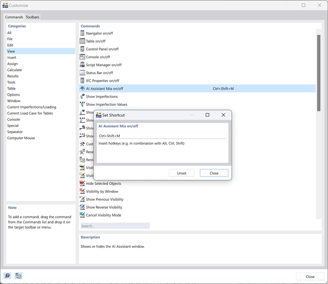
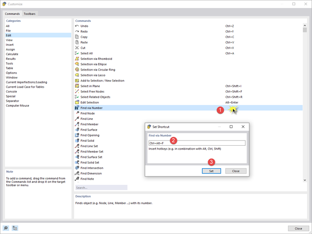
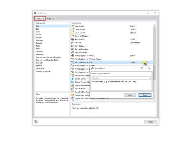
Changing Mia's Shortcut
The keyboard shortcut of the AI assistant Mia conflicts with another shortcut that I use in the system. How can I change the Mia shortcut?
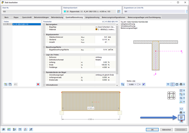
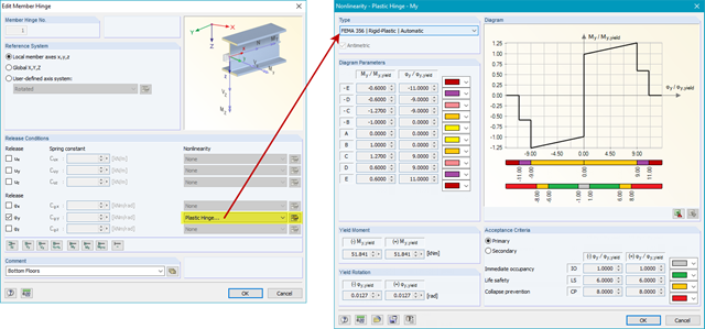
Graphic Templates for Printing Reinforcement Layout
How can I use graphic templates for multi printing of a reinforcement?
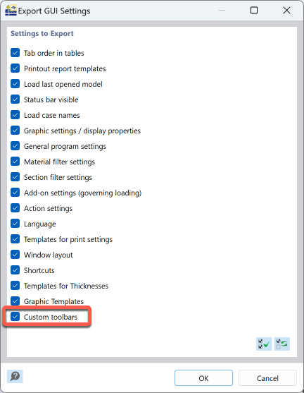
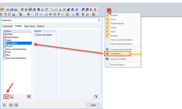
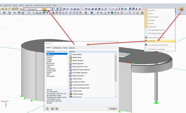
Saving Toolbars
I have customized my toolbars. How can I save these settings to use them on another computer?
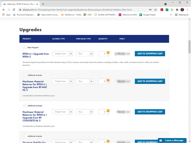
Upgrade to RFEM 6 / RSTAB 9 with RFEM 5 Service Contract
Can I upgrade to RFEM 6 or RSTAB 9 for free with my current RFEM 5 or RSTAB 8 service contract?
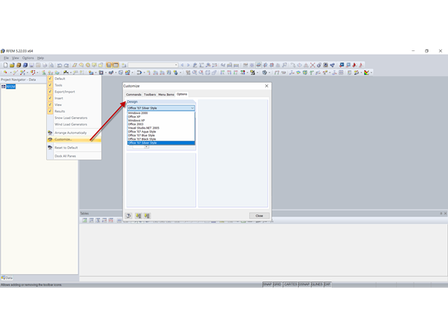
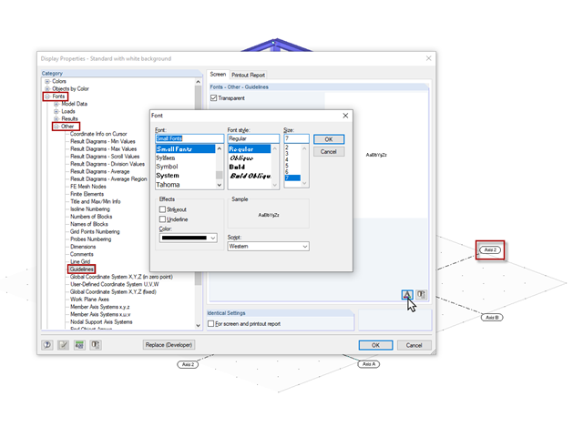
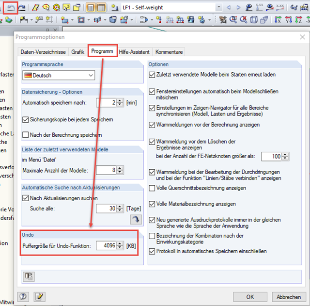
Question
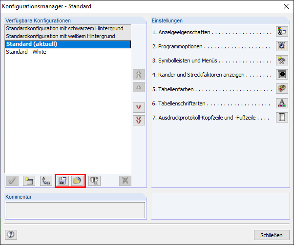
How can I change the design of the program interface?
Program Packages
Can I compile special program packages at Dlubal Software?

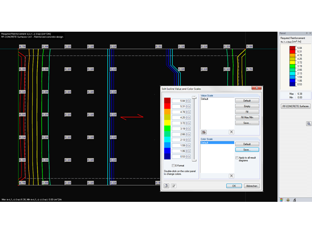
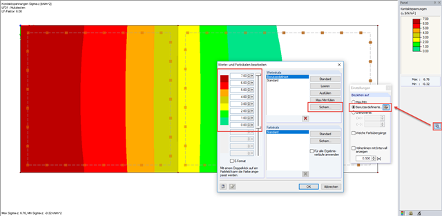
Question
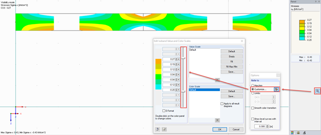
Is it possible to freely define the numerical values of isoline intervals (for example, result display of the isolines for the bottom reinforcement as1 in steps of 5.0 cm²/m)?
Question
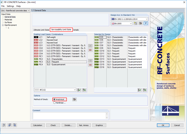
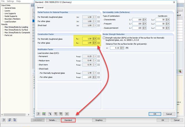
Is it possible in the RF‑CONCRETE Surfaces add-on module to limit crack widths due to internal restraint and with the customized fct,eff?
Question
There are no result values displayed in the table for the individual surfaces. Why?
Question
Is it possible to transfer a user-defined value spectrum to all load cases or load combinations?
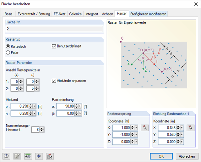
Question
Is there a possibility to show results only for a customized area?
Question
Can I adjust the width of the drop-down list box for selecting load cases and combinations?